




The Screen as a Precision Light Valve
When specifying digital signage, medical displays, or control room video walls, engineering teams frequently ask a straightforward question: what are monitor screens made of?
To the end user, a modern screen display appears as a seamless, dark sheet of glass that springs to life with vibrant color. From a materials science standpoint, however, an active-matrix display panel is neither a single pane of glass nor a self-glowing panel. Liquid crystals emit no light of their own.
Instead, an industrial liquid crystal display functions as a multi-layer optical light valve. It generates raw white light at the back, converts it into neat linear light waves, twists those waves using electrical voltages, separates them into primary red, green, and blue wavelengths, and resolves contrast through a secondary optical filter.
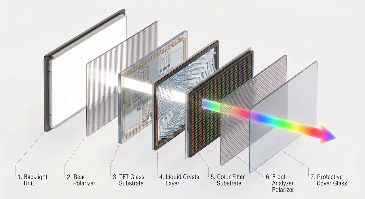
Every layer in this stack uses specialized chemical polymers, inorganic glasses, and semiconductor compounds selected for high optical clarity, heat tolerance, and structural endurance.
Deconstructing the 7-Layer Material Stack
An industrial TFT-LCD panel consists of seven primary physical layers assembled with sub-micron precision.
1. The Backlight Module and Optical Films
Because liquid crystals are completely passive, every standard LCD relies on a dedicated Backlight Unit to create brightness. High-efficiency blue InGaN LEDs paired with yellow YAG phosphors generate raw white light.
This light enters an optical light guide plate made of high-purity PMMA acrylic or polycarbonate. Microscopic laser-etched patterns on the plate bounce the light outward into an even, planar glow, while micro-prism sheets made of PET polymer focus the light toward the viewer, delivering sustained outputs ranging from 250 nits for indoor monitors to over 3,500 nits for outdoor digital signage.
2. The Rear Linear Polarizer
Raw LED light vibrates in all directions perpendicular to its path. The rear polarizer cleans up this chaos.
Manufactured by stretching a polyvinyl alcohol film and infusing it with linear iodine chains, this layer blocks all out-of-phase waves and only lets through light vibrating along a single horizontal axis. Dual outer layers of triacetyl cellulose protect this delicate film from humidity and mechanical damage.
3. The TFT Array Glass Substrate
The electronic brain of the panel sits on a specialized sheet of boro-aluminosilicate glass, typically 0.3mm to 0.7mm thick.
This glass must be completely alkaline-free. Ordinary glass contains mobile sodium and potassium ions that would migrate into the electronics under high manufacturing temperatures and cause permanent electrical shorts.
On top of this high-purity glass, manufacturers sputter transparent Indium Tin Oxide electrodes and millions of microscopic thin-film transistors made of amorphous silicon or IGZO to deliver precise voltage signals to every sub-pixel.
4. The Nematic Liquid Crystal Layer
Held in a microscopic gap between 3.0 and 4.0 microns wide, the liquid crystal layer contains rod-shaped organic molecules with unique optical properties. Polyimide alignment coatings ensure these molecules rest in an orderly pattern.
When voltage passes between the transparent electrodes, the molecules rotate, creating a precise optical phase twist that rotates passing light anywhere from 0 to 90 degrees.
5. The Color Filter Substrate
To transform modulated white light into rich images, each individual lcd pixel is split into red, green, and blue sub-pixels.
On a second sheet of alkaline-free glass, a microscopic grid known as the Black Matrix is etched to block stray light between channels. Highly stable acrylic resins mixed with nanoscale red, green, and blue organic pigments are then photolithographically cured onto the glass, giving each sub-pixel its distinct color filter.
6. The Front Analyzer Polarizer
The front polarizer is identical in material composition to the rear polarizer, but its transmission axis is turned at an exact 90-degree angle.
It acts as the final gatekeeper of the light valve. Light that was twisted by the liquid crystal layer passes straight through to create bright pixels, while untwisted light is completely absorbed to create deep, clean blacks. The outer surface is treated with anti-glare etching or anti-reflective coatings to minimize room reflections.
7. Protective Cover Glass
Commercial and interactive installations often bond a final sheet of chemically strengthened glass to the front of the display using solid optical clear adhesives or liquid resins. This protective barrier delivers surface hardness between 7H and 9H, shielding the optical stack from daily impacts and heavy public use.
While understanding raw chemistry is essential for evaluating optical quality, these glass substrates and optical films must eventually integrate into a complete mechanical and electronic frame. If you want to see how this optical stack connects with timing controllers, driver ICs, and outer bezels, take a look at our complete architectural breakdown of the parts of an LCD screen.
Optical Performance and Material Comparison
The choice of glass and polarizers remains fairly consistent across the industry, but the exact way liquid crystal molecules are aligned inside the cell determines your final contrast, response speed, and color shift. We have broken down the practical differences in our guide comparing TFT-LCD panel types like IPS, VA, and TN.
| Engineering Metric | IPS Panels | VA Panels | TN Panels | Industrial Baseline |
| Glass Substrate | 0.5mm Alkaline-Free Glass | 0.5mm Alkaline-Free Glass | 0.7mm Borosilicate Glass | Low thermal expansion |
| Molecular Motion | Horizontal planar rotation | Multi-domain vertical tilt | 90-degree spiral twist | Cell gap 3.2 to 3.8 microns |
| Static Contrast | 1,000:1 to 2,000:1 | 3,000:1 to 5,000:1 | 700:1 to 1,000:1 | 1,000:1 minimum for control rooms |
| Sustained Brightness | 350 to 1,500+ nits | 300 to 1,000+ nits | 250 to 400 nits | 1,500+ nits for outdoor use |
| Response Time | 4ms to 8ms with overdrive | 4ms to 12ms | 1ms to 2ms native fast | 8ms or faster for touch UI |
| Viewing Angles | 178 degrees, zero shift | 178 degrees, minor shift | 170 by 160 degrees | 178 degrees for public displays |
| Light Transmittance | 3.5% to 4.5% | 4.0% to 5.0% | 5.0% to 6.0% | Directly impacts backlight power |
The Reality of Optical Attenuation
A finished LCD panel is a high-attenuation optical filter. As light travels from the internal LEDs toward the viewer:
- The rear polarizer absorbs roughly 55% of raw photonic energy.
- Metal bus lines and transistor circuits on the TFT glass block another 40% of the remaining light.
- The red, green, and blue color filter resins absorb 70% of the spectral energy to isolate pure wavelengths.
- The front polarizer and glass boundaries absorb and reflect a further 15%.
Consequently, only 4.5% to 7.0% of the backlight's original output ever reaches the human eye. To produce a sunlight-readable 2,500-nit commercial display, the internal backlight must generate over 40,000 nits of raw optical energy, requiring heavy-duty aluminum thermal backplates to shed excess heat.
Reliability and Lifespan in Continuous 24/7 Operations
For enterprise deployments, material durability under continuous thermal and electrical load directly dictates Total Cost of Ownership.
Inorganic Glass Stability vs. Organic Burn-In
OLED screens rely on organic light-emitting polymers that degrade unevenly over time, leading to permanent burn-in when displaying static user interfaces.
In contrast, TFT-LCD panels are built from inorganic glass substrates, stable metal-oxide conductors, and highly resilient liquid crystal compounds. Static graphics like security surveillance grids, industrial telemetry, or flight arrival boards can run non-stop for years without permanent image ghosting.
50,000 to 100,000-Hour Operating Lifespan
Because liquid crystals undergo no physical degradation from electrical switching, the operational lifespan of an LCD module is determined almost entirely by the solid-state LED backlight. Commercial-grade displays easily achieve 50,000 to 100,000 hours of service before luminance drops to 70% of its original rating, delivering between 6 and 11 years of continuous, non-stop operation.
Preventing Polarizer Degradation and Solar Blackout
In hot, humid environments, low-grade polarizers can absorb moisture, causing the iodine molecules to break down and wash out screen contrast. Commercial screens prevent this by sealing the polarizer core with hydrophobic barrier films.
Similarly, screens exposed to direct summer sunlight can easily reach internal temperatures above 70°C. Standard consumer liquid crystals lose their alignment at these temperatures and collapse into dark blotches on the screen. Industrial outdoor panels utilize wide-temperature liquid crystal formulations with a clearing point above 110°C, ensuring the screen remains fully operational even under intense solar exposure.
Custom Hardware and Manufacturing Options
Beyond standard panel sizing, commercial displays require tailored mechanical, optical, and electronic integration to match specific field environments:
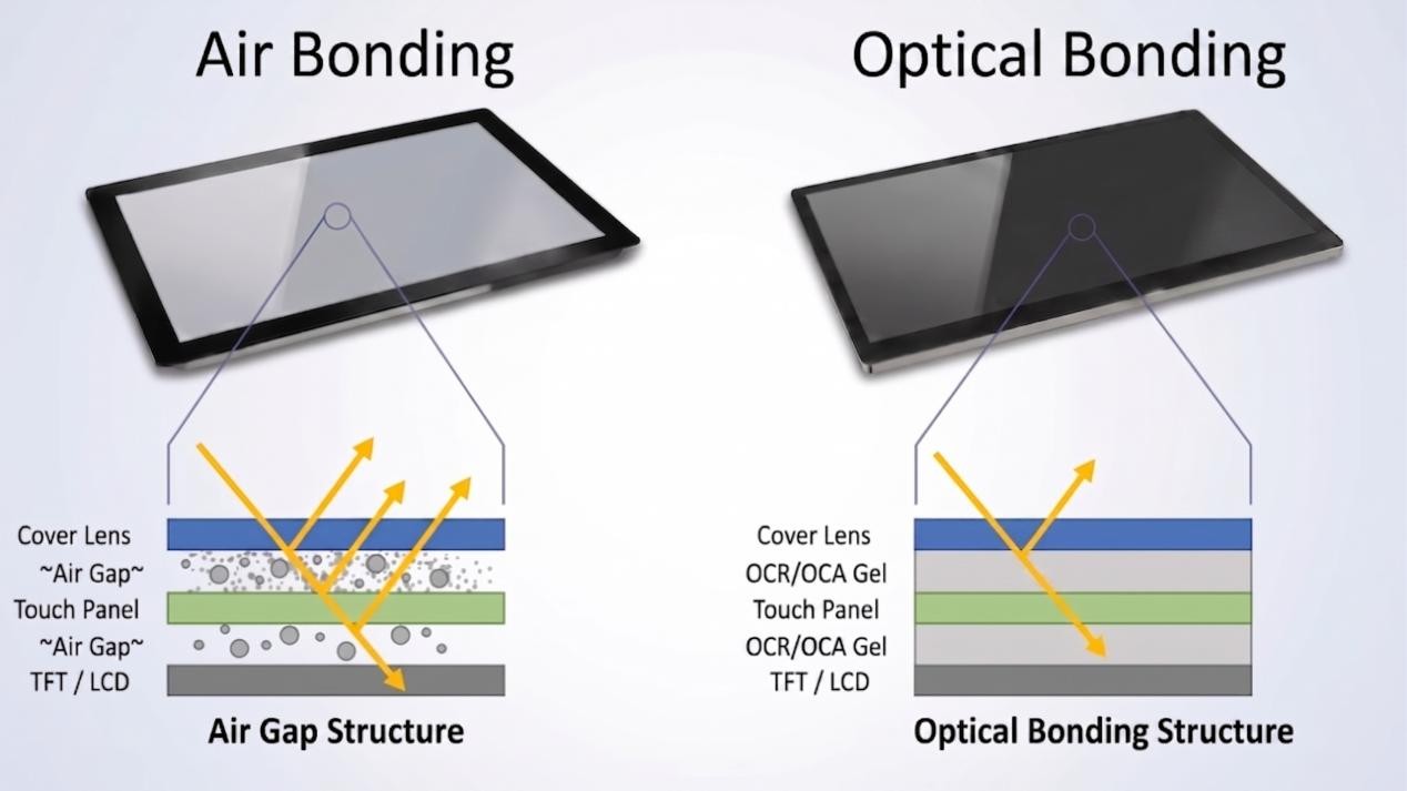
- Optical Lamination Choices: Deployments exposed to bright lighting benefit from full optical bonding using solid OCA or liquid OCR adhesives under 1mm thick, which eliminates the internal air gap, cuts surface reflections to 0.2%, and prevents internal condensation. For budget-sensitive indoor projects, perimeter frame bonding maintains a narrow 2mm air gap for cost-effective assembly and simple maintenance.
- Interactive Touch Architectures: Commercial touchscreens utilize slim G+FF capacitive touch sensors for lightweight single-screen kiosks, heavy-duty G+G dual-glass builds for scratch-resistant public terminals, or nano metal mesh and infrared frames for expansive multi-panel video walls up to 110 inches.
- Chassis and Thermal Engineering: High-power outdoor units use heavy-duty sheet metal enclosures for maximum impact strength and rapid heat dissipation, while indoor terminals adopt anodized aluminum profiles for clean lines and lightweight installation.
- Modular Driving and Compute: Ultra-slim kiosks can separate the power supply, T-Con board, and embedded Android or Windows OPS computers into an external driver box, using shielded high-speed coaxial cables to transmit video signals over long distances without signal degradation.
Custom Commercial Display Sourcing
Whether sourcing embedded touch modules for retail kiosks or engineering high-brightness video walls, selecting the right glass substrates, optical coatings, and thermal architecture ensures your displays perform reliably for years in the field. Contact our engineering team to request detailed component drawings, 3D CAD models, optical simulations, or evaluation samples.
FAQ
Why do LCD screens require two polarizing filters? Can an image form with only one?
An LCD cannot work with a single polarizing filter. A single polarizer only aligns raw backlight into an orderly linear wave. Liquid crystals do not generate colors or block light on their own—they simply rotate the physical angle of that light wave.
A second polarizer, placed at a right angle to the first, is mathematically required to turn those rotational shifts into visible variations in brightness. Without that second front polarizer, you wouldn't see an image at all—just a wash of uniform white glare. If you want to follow the step-by-step physics of how voltage pulses steer light through this gate, we walk through the entire cycle in our guide on how an LCD works.
How are microscopic RGB sub-pixels manufactured on the glass?
Sub-pixels are fabricated using cleanroom photolithography:
- An opaque Black Matrix grid made of chromium or black resin is etched onto alkaline-free glass to define pixel boundaries.
- Acrylic negative photoresists infused with nanoscale red organic pigments are coated across the surface.
- High-precision ultraviolet steppers expose the photoresist through photomasks to cure the red sub-pixel lines.
- Unexposed resin is washed away in developer fluid, and the red lines are baked at 230°C.
- This process is repeated for green and blue resins, creating millions of precise RGB sub-pixel groupings across the substrate.
Why must TFT array substrates use alkaline-free glass?
Standard window glass contains high levels of mobile sodium and potassium ions. During thin-film transistor manufacturing, temperatures reach between 350°C and 450°C. Under these temperatures and operating electrical fields, sodium ions migrate directly into the silicon semiconductor channels.
This causes electrical leakage, shifts the transistor threshold voltage, and permanently ruins pixel switching. High-purity boro-aluminosilicate glass contains no alkali metals, ensuring long-term electrical reliability and structural stability through thermal cycles.