




Overview: What Are the Main Components and Parts of an LCD Display?
When sourcing or designing screens for commercial equipment, understanding an LCD goes far beyond the glass. In the display manufacturing industry, a finished display unit is called a Liquid Crystal Module (LCM).
An LCD does not generate light on its own. It functions as an electrically controlled light valve that shapes background light into images. A complete commercial LCD module integrates four synchronized hardware systems:
- The Open Cell (Raw Glass Panel): The central glass sandwich that controls light passage and produces color.
- The Drive & Control Electronics: The high-speed microchips and ribbon cables that translate digital video inputs into pixel voltages.
- The Backlight Unit (BLU): The light engine that generates a flat, bright, uniform field of pure white light.
- The Structural Housing: The precision metal frame, thermal interface pads, and protective cover glass that shield the components from physical and thermal stress.
The 7-Layer Panel Stack-up: What Are the Layers Inside an LCD Panel?
The core optical engine of every LCD screen is the Open Cell. This multi-layer assembly stacks seven functional layers together within a thickness of just 1 to 2 millimeters:
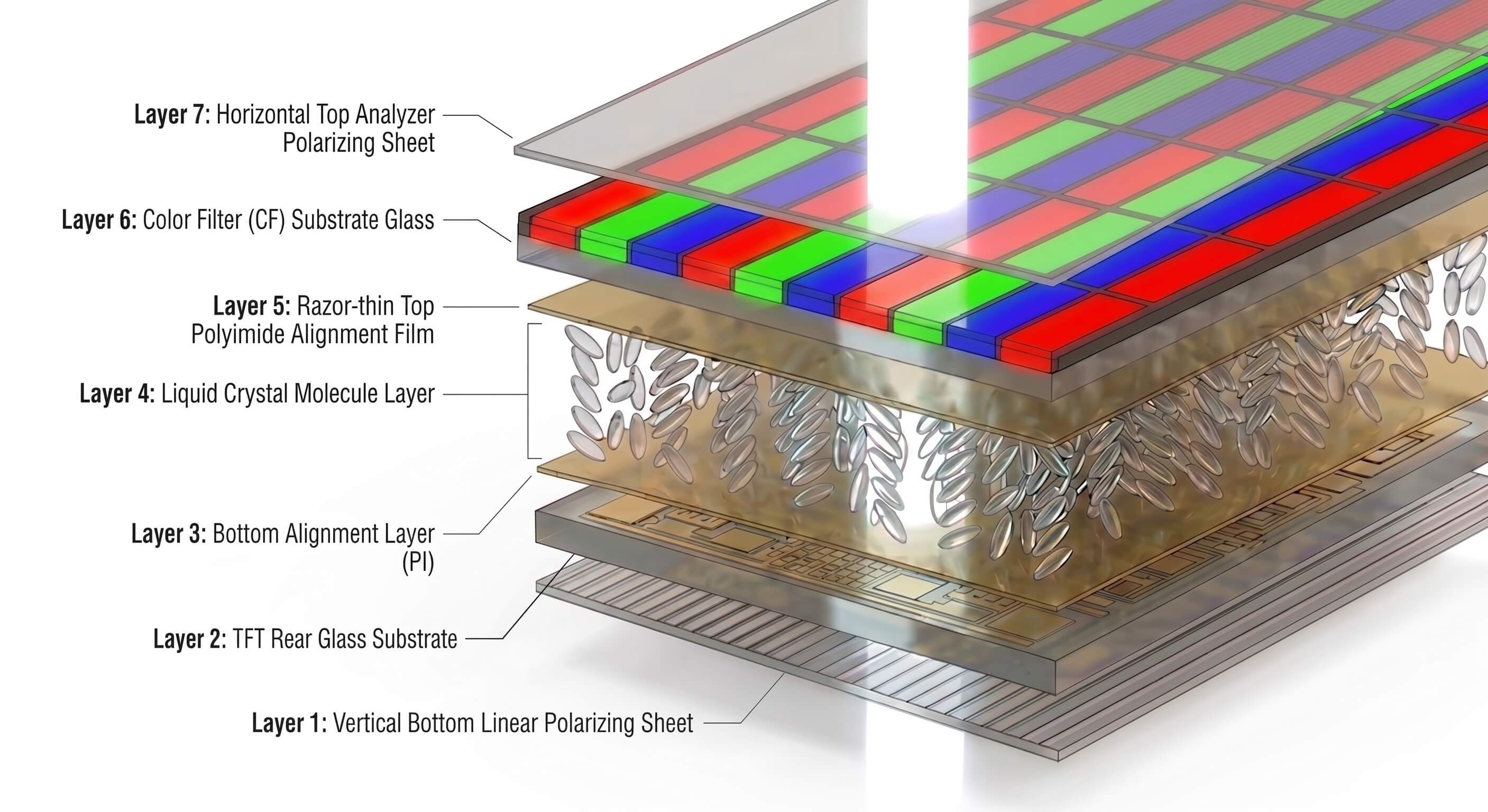
The 7 Layers Explained
- Rear Polarizing Film: Filters random, unpolarized backlight rays so only vertically oriented light waves pass through.
- TFT Rear Glass Substrate: An ultra-thin sheet of non-alkaline borosilicate glass holding millions of microscopic Thin-Film Transistors (TFT) and transparent electrode pads.
- Bottom Alignment Layer: A polymer coating with microscopic grooves that lines up the resting liquid crystal molecules in a fixed starting direction.
- The Liquid Crystal Layer: The fluid core of the display. Suspended inside a gap thinner than a red blood cell, these molecules rotate light waves when relaxed and let them pass straight through when charged with electricity.
- Top Alignment Layer: Works with the bottom alignment layer to maintain uniform molecular orientation across the entire glass surface.
- Color Filter Substrate: High-precision glass coated with microscopic Red, Green, and Blue resin filters. An opaque Black Matrix grid surrounds each colored square to stop colors from bleeding into neighboring pixels.
- Front Polarizing Film (The Analyzer): Positioned with its filter lines running horizontally (90 degrees opposite to the rear polarizer). It only allows light through if the liquid crystal layer twisted the wave to match its opening.
For a deeper look into the physics of light polarization and optical ray paths, explore our companion technical guide on how LCD screens and backlights work.
What Role Does the Liquid Crystal Layer Play Between Glass Substrates?
The liquid crystal layer serves as an electronically controlled light valve.
Because liquid crystals are fluid materials with crystal-like optical properties, their molecular orientation shifts whenever an electrical voltage is applied across them (taking a standard Twisted Nematic / TN panel as a primary example):
- When Power is Off: The molecules rest in a natural twist. When light enters from the rear polarizer, the twisted molecules guide the light wave, turning it 90 degrees so it slips directly through the front polarizer at maximum brightness.
- When Power is On: The electric field pulls the molecules upright. The light passes straight through without twisting, hits the front polarizer at the wrong angle, and is completely blocked, creating a deep black state.
Classic Twisted Nematic (TN) panels are best known for their fast pixel response times and cost-effective manufacturing, though they have narrower viewing angles and noticeable color shifting when viewed off-axis. Beyond standard TN, modern LCD displays also rely on other specialized molecular alignment technologies—such as Vertical Alignment (VA), which excels at delivering deep, ink-like blacks and high static contrast ratios, and In-Plane Switching (IPS), which provides ultra-wide 178-degree viewing angles and superior color accuracy from any direction. Choosing between these technologies depends entirely on your specific application scenarios and performance requirements. (If you are interested in learning more about how these panel types work and how to select the right one for your project, please refer to our in-depth guide on TFT-LCD panel types: IPS vs. TN vs. VA.)
By adjusting the voltage across each microscopic sub-pixel, the system can tilt the molecules to any intermediate angle. This controls the exact percentage of light passing through each Red, Green, and Blue sub-pixel, allowing the screen to blend millions of distinct colors with smooth grayscale control.
Drive & Control Electronics: From T-Con Boards to Driver ICs and Ribbon Cables
Without external driving hardware, the Open Cell glass cannot receive or process video signals. The driving architecture acts as the screen's nervous system:
1. Timing Controller (T-Con Board)
The T-Con board is the primary logic computer of the display. It receives incoming video streams (such as LVDS, eDP, or V-by-One) from your media player or mainboard. It splits the high-speed image stream into discrete row-timing pulses and column-voltage values, ensuring every pixel refreshes at the exact same microsecond.
2. Driver ICs (Gate & Source Drivers)
- Gate Drivers (Row Drivers): Turn on entire horizontal lines of pixel switches one row at a time.
- Source Drivers (Column Drivers): Deliver precise analog voltages down the vertical columns to charge the sub-pixel electrodes to their intended brightness level.
3. Chip-on-Glass (COG) vs. Chip-on-Film (COF) Packaging
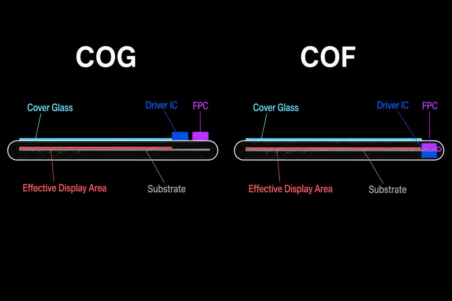
- Chip-on-Glass (COG): Driver chips are mounted directly onto the edge of the LCD glass substrate. This architecture is rigid, cost-effective, and standard for compact handhelds, smart meters, and industrial touch terminals.
- Chip-on-Film (COF): Driver chips are mounted onto flexible polyimide ribbon tape. The flexible tape can bend 180 degrees around to the back of the panel chassis, enabling ultra-slim bezels on video walls, narrow-border monitors, and commercial digital signage.
4. Flexible Printed Circuit (FPC) Ribbon Cables
FPC cables are durable, heat-resistant polyimide cables with high-density gold-plated connector pins. They route high-speed digital signals and power rails from the mainboard to the driver chips while resisting electrical noise and mechanical vibration.
The Backlight Unit (BLU) and Mechanical Chassis Frame
Because the LCD glass is purely a light filter, the Backlight Unit (BLU) supplies the raw white illumination:
- LED Light Engine: High-efficiency LED bars mounted along the inner frame edges (Edge-lit) for ultra-thin designs, or arranged in an array across the rear backplate (Direct-lit) for high-brightness and local dimming performance.
- Light Guide Plate (LGP): A specialized optical PMMA acrylic sheet covered with precision-etched micro-dots that channels light from edge LEDs and turns it into a uniform, forward-facing light field.
- Optical Film Pack: Combines a Reflector Sheet (recovers lost light from the bottom), a Diffuser Sheet (smooths out glare spots), and dual Prism Sheets (microscopic optical ridges that focus wide-angle light forward to double on-axis brightness).
- Structural Metal Chassis: A rigid frame made of stamped galvanized steel (SECC) or extruded aluminum that secures the optical films, shields against electromagnetic interference (EMI), and draws heat away from the LEDs and driver chips.
LCD Component Specification Matrix: Materials, Functions, and Sourcing Insights
| Component / Layer | Typical Thickness | Standard Material | Primary Function | Engineering & Sourcing Insight |
| Cover Glass (Optional) | 0.5 mm – 3.0 mm | Chemically Strengthened Glass | Shields against impacts, scratches, and liquids | Specify Anti-Glare (AG) or Anti-Reflective (AR) etching for outdoor sunlight readability. |
| Front & Rear Polarizers | 0.15 mm – 0.20 mm | Iodine-doped PVA film with TAC support | Filters light wave angles to enable image modulation | High-humidity installations require sealed edges to prevent polarizer delamination or bubbling. |
| Color Filter (CF) Glass | 0.4 mm – 0.7 mm | Non-alkaline glass + RGB acrylic resin | Separates white light into Red, Green, and Blue | Absorbs approximately two-thirds of light; high-bright screens require stronger backlights to compensate. |
| Liquid Crystal Layer | ~3.5 microns | Formulated nematic liquid crystal fluid | Operates as a voltage-controlled light valve | For outdoor direct sunlight, specify high-temperature (>105℃) fluid to prevent dark spots. |
| TFT Array Substrate | 0.4 mm – 0.7 mm | Borosilicate glass + patterned metal circuits | Provides independent electrical switches for every pixel | Higher aperture ratios allow more light through, improving energy efficiency and lowering heat. |
| Driver ICs (COF/COG) | Microscopic silicon die | Silicon microchip on polyimide film | Converts digital video data into pixel drive voltages | High-resolution displays generate heat at the drivers; ensure direct thermal pad contact to the chassis. |
| Backlight Unit (BLU) | 1.0 mm – 15.0 mm | LEDs + PMMA light guide + optical prism films | Generates uniform, high-brightness white planar light | Commercial indoor use requires 350–700 nits; outdoor sun-exposed setups require 2,500–3,500 nits. |
Total System Light Efficiency in Practice
Understanding total system light efficiency is essential when designing and sourcing commercial displays. Starting with 100% of the raw white light generated by the backlight LEDs, more than half is immediately absorbed as it enters the rear polarizing film, leaving roughly 42%. As this light travels through the TFT glass substrate, the microscopic metal circuits and transistor grid block an additional portion, reducing the available light to about 30%.
Finally, the Red, Green, and Blue color filters absorb roughly two-thirds of the remaining light spectrum to create accurate colors, leaving only 6% to 8% of the total light to actually reach the viewer's eyes. Because an LCD panel naturally blocks over 90% of the light produced inside it, sourcing a high-efficiency backlight unit paired with an effective thermal dissipation housing is critical for achieving clear, high-brightness performance in outdoor and commercial environments.
Component Reliability: Common Hardware Failure Modes and Thermal Protection
1. Vertical Lines on Screen (Driver IC Failure)
A solid vertical line or missing color stripe across the screen points to a faulty connection along the Source Driver IC or the FPC ribbon cable.
- High operating temperatures can degrade the conductive bonding adhesive on the glass edge over years of use.
- Engineering Solution: Use thermally conductive gap pads between the driver ICs and the aluminum frame to keep junction temperatures well within safe limits.
2. Backlight Bleed (Mechanical Bezel Stress)
Noticeable light glow around the dark edges of an LCD is usually caused by mechanical stress rather than an optical defect in the glass.
- If a display bezel is fastened unevenly, it pinches the Open Cell, distorting the uniform 3.5-micron gap between the glass sheets and letting light leak through.
- Engineering Solution: Use precision CNC-milled aluminum chassis with high-elasticity cushion foam gaskets to isolate the glass from external torque and frame warping.
3. Solar Black Spots (Direct Sunlight Clearing)
When standard indoor monitors are installed in outdoor kiosks, intense solar heat can easily push the internal panel temperature above 80°C.
- At this threshold, standard liquid crystal fluid temporarily loses its structured alignment and turns into a simple liquid, creating large, dark blotches across the display.
- Engineering Solution: Specify High-Temperature Industrial Liquid Crystals rated to withstand operating temperatures of 105°C or higher without blacking out.
B2B Sourcing Guide: Open Cell vs. LCM and Customization Options
Sourcing Strategy: Open Cell Glass vs. Complete LCM
When planning your procurement strategy, the choice between sourcing raw Open Cell glass and purchasing a complete Liquid Crystal Module (LCM) comes down to your internal manufacturing capabilities and project timeline:
- Sourcing Raw Open Cell Glass: This option is best suited for experienced OEM and ODM manufacturers equipped with cleanroom assembly facilities. Buying raw Open Cell glass provides maximum engineering freedom to integrate custom high-brightness backlights, specialized thermal systems, and proprietary enclosures while optimizing overall bill-of-materials (BOM) costs.
- Sourcing a Complete LCM Module: This route is ideal for system integrators and equipment builders looking for a verified, plug-and-play solution. Because the module arrives fully assembled with factory-calibrated LED backlights, driver boards, ribbon cables, and rigid mounting frames, it eliminates cleanroom assembly requirements, lowers technical integration risk, and significantly shortens your time-to-market.
Customization Options for Commercial Deployments
- Optical Bonding (Full Lamination): Standard screens leave a small air gap between the outer cover glass and the LCD panel, causing reflections, glare, and trapped condensation. Optical bonding fills this gap with an optically clear adhesive, eliminating internal reflections, boosting impact resistance to IK08/IK10, and making screens readable in direct sunlight.
- High-Brightness Backlight Upgrades: Replacing standard 350-nit indoor backlights with custom aluminum LED matrix light engines delivering 1,500 to 3,500 nits of sustained daylight-visible brightness.
- Custom FPC Cable Engineering: Custom cable lengths, right-angle bend tooling, and electromagnetic interference (EMI) gold shielding to ensure seamless fit inside tight enclosures.
Request Engineering Specifications & Custom Samples
Designing an industrial display system or ruggedized commercial product requires tight tolerances, proven thermal dissipation, and long-term supply stability. Contact our display engineering team to review 2D/3D CAD drawings, evaluate custom driver architectures, or request optical bonded LCM engineering samples.
FAQ
What are the main components and parts of an LCD display?
A complete commercial LCD display module contains four main systems:
- The Open Cell: The glass assembly containing the thin-film transistors (TFT), color filters, transparent electrodes, and liquid crystal fluid.
- The Backlight Unit (BLU): The light engine made of LED arrays, light guide plates, reflectors, and brightness-boosting prism films.
- Driving Circuitry: The Timing Controller (T-Con) board, Driver ICs (COG or COF), and flexible printed circuit (FPC) cables.
- Mechanical Housing: A metal back chassis (aluminum or steel), shock-absorbing cushion gaskets, and a front bezel or cover glass.
What are the layers inside an LCD panel stack-up?
From back to front, the 7 functional layers inside the Open Cell are:
- Rear Polarizing Film: Aligns unpolarized backlight rays into a single wave direction.
- TFT Rear Glass Substrate: Holds millions of microscopic switches and pixel electrodes.
- Bottom Alignment Layer: Sets the baseline resting angle for the liquid crystal molecules.
- Liquid Crystal Layer: Acts as precision, voltage-controlled light valves.
- Top Alignment Layer: Keeps the upper boundary of the liquid crystal fluid aligned.
- Color Filter Substrate: Red, Green, and Blue sub-pixel filters framed by a Black Matrix grid.
- Front Polarizing Film: Acts as the light analyzer to pass or block light based on how it was rotated.
What role does the liquid crystal layer play between glass substrates?
The liquid crystal layer acts as an electrically controlled light valve. Because liquid crystal molecules change their physical orientation when voltage is applied, they can twist light waves when relaxed or allow them to pass straight through when energized.
By varying the voltage on each sub-pixel, the screen precisely controls how much light reaches the front polarizer, smoothly adjusting brightness from deep black to full color across millions of points on screen.
What is the difference between an LCD panel (Open Cell) and an LCD module (LCM)?
- Open Cell (LCD Panel): Just the raw glass sandwich—the two glass sheets, liquid crystals, color filters, and polarizers. It cannot show an image on its own because it has no backlight or housing.
- LCM (LCD Module): A complete, ready-to-use display unit. It combines the Open Cell with the backlight unit, metal housing frame, driver chips, and input ribbon cables.
What is the difference between COG (Chip-on-Glass) and COF (Chip-on-Film)?
- COG (Chip-on-Glass): The driver microchips are mounted directly onto the surface of the extended LCD glass. This design is rugged, cost-effective, and common in compact screens and standard monitors.
- COF (Chip-on-Film): The driver microchips are mounted onto a flexible polyimide ribbon film. The film can bend 180 degrees around to the back of the panel, allowing for ultra-slim bezels on video walls and high-end digital signage.