

Understanding Character LCD Fundamentals
Character LCDs such as 16x2 and 20x4 modules remain one of the most widely used human-machine interfaces in embedded systems. Their standardized structure makes them reliable, cost-effective, and easy to integrate into control panels, instruments, and industrial devices.
Unlike raw segment displays, character LCDs typically include an internal controller. This controller simplifies programming by handling character generation, memory mapping, and display timing internally.
Hardware Architecture and Pin Configuration
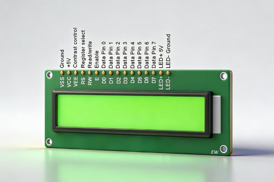
Character LCD modules usually feature 14 pins, or 16 pins when a backlight is included. Each pin plays a defined role in power delivery, signal control, or data transmission.
Power and Contrast Control
VSS connects to ground and serves as the reference level.
VDD supplies logic voltage, commonly 5V or 3.3V.
VO adjusts contrast by varying the voltage between VDD and ground, often through a potentiometer.
Control Pins
RS selects between instruction and data registers.
RS set low sends commands.
RS set high sends display data.
RW controls read or write mode.
RW low writes to the display.
RW high reads status or data.
In many applications, RW is tied to ground to simplify hardware.
E, or Enable, latches incoming data.
A stable data state followed by a high-to-low pulse locks the byte into the controller.
Data Bus
D0 through D7 form the parallel data bus.
In 8-bit mode, all eight bits transfer at once.
In 4-bit mode, only D4 through D7 are used. Data transfers in two steps — high nibble first, then low nibble. This approach reduces MCU I/O usage.
Backlight Control
Pins A and K power the LED backlight.
Separating backlight power from logic power improves long-term stability and reduces electrical noise.
Controller Architecture and Memory Model
Most character LCDs use the HD44780 controller or a compatible chip. Understanding its internal memory structure is essential for accurate programming.
DDRAM — Display Data RAM
DDRAM stores the character codes currently shown on the screen.
For a 16x2 module:
- First line addresses range from 0x00 to 0x0F
- Second line addresses range from 0x40 to 0x4F
Writing an ASCII value to a DDRAM address displays the corresponding character at that position.
The Address Counter automatically increments or decrements based on the selected Entry Mode.
CGROM — Character Generator ROM
CGROM contains predefined character patterns including letters, digits, and symbols.
Sending an ASCII code to DDRAM automatically calls the matching pattern from CGROM.
For example, sending 0x41 displays the character A.
CGRAM — Character Generator RAM
CGRAM allows custom character creation.
Up to eight 5x8 custom characters can be defined.
Programming CGRAM involves:
- Setting the CGRAM address
- Writing 8 bytes representing the dot pattern
- Calling the assigned code from DDRAM
This feature enables simple icons, indicators, or logos without additional graphics hardware.
Instruction Set and Communication Logic
Communication with a character LCD involves writing commands or data to specific registers.
Core Command Categories
Clear Display resets DDRAM and returns the cursor home.
Return Home moves the cursor without altering DDRAM.
Entry Mode Set defines cursor direction and optional display shift.
Display Control toggles display, cursor visibility, and blink settings.
Cursor or Display Shift moves content without modifying memory.
Function Set defines:
- 4-bit or 8-bit interface
- Number of lines
- Character font
4-Bit Communication Process
In 4-bit mode, each byte transmits in two cycles.
- Place the high four bits on D4-D7
- Pulse Enable
- Place the low four bits on D4-D7
- Pulse Enable again
The controller combines both halves into a full byte.
From Embedded Displays to Commercial Display Systems
Character LCDs represent the foundation of embedded display systems. Modern commercial display environments build upon similar communication principles but operate at significantly higher complexity.
Driver Evolution
Embedded LCDs use MCU-level parallel buses.
Commercial displays rely on HDMI, LVDS, or eDP interfaces driven by high-performance SoCs.
Content Management
Embedded systems display firmware-defined content.
Commercial digital signage integrates network-based Content Management Systems for remote updates and scheduling.
Display Technology Advancements
Traditional LCD panels remain dominant for indoor commercial applications.
Transparent OLED introduces light transmission alongside digital content, allowing displays to integrate into glass façades, retail showcases, and exhibition environments.
Higher transparency improves indoor lighting conditions but reduces pixel density. The balance depends on project goals.

Key Considerations in Commercial Display Engineering
Uniformity and Reliability
Video walls must maintain consistent brightness and color across panels.
Hardware binning reduces variation. Software-based LUT calibration ensures synchronized color performance.
Installation Environment
Indoor environments protect display modules and stabilize brightness performance.
Outdoor installations require enhanced IP protection, brightness compensation, and structural wind resistance.
System Integration
Modern commercial display systems often integrate sensors, cameras, and AI engines.
Interactive systems shift from passive broadcasting to responsive user engagement.
FAQ
Q1: What are the most basic steps when initializing a character LCD?
Initialization typically includes a power-on delay, Function Set configuration, Display Off command, Clear Display, Entry Mode Set, and finally Display On. This sequence ensures stable startup and predictable controller behavior.
Q2: How do you display a custom logo or special symbol on a character LCD?
Use CGRAM to define custom patterns. Set the CGRAM address, write eight bytes for a 5x8 character, then call the assigned code from DDRAM. This enables simple icons without additional graphics hardware.
Q3: Why are two Enable pulses required in 4-bit mode?
In 4-bit mode, data transfers occur in two stages. The MCU sends the upper four bits, pulses Enable, then sends the lower four bits and pulses again. The controller combines both halves into one byte.
Q4: How can commercial video walls maintain consistent brightness and color?
Consistency requires hardware binning and software calibration. High-uniformity modules reduce variation, while LUT-based color calibration ensures synchronized brightness and color across panels.
Q5: What distinguishes Transparent OLED from traditional LCD in commercial use?
Transparent OLED allows light transmission while displaying content, enabling integration into windows and showcases. Traditional LCD panels are opaque and better suited for fixed digital signage installations.
RUSINDISPLAY focuses on professional Transparent OLED and high-performance LCD solutions for commercial environments. By combining reliable display hardware with practical integration expertise, RUSINDISPLAY supports retail, exhibition, and architectural projects that require stable performance and intelligent visual presentation.